Low outlet-air temperature is only a symptom: the exchanger may be receiving too little gas, losing flow through a bypass, measuring temperature incorrectly, or transferring less heat because of fouling and damage. You will be able to separate those causes with a heat balance, matched flow and pressure readings, and targeted inspections before approving cleaning or repair.
Key takeaways
- Calculate heat duty on both air and flue-gas sides before replacing equipment.
- Use pressure-drop changes and inspection evidence to locate fouling.
- Test fans, dampers, draft and bypass leakage while the system carries load.
- Control cold-end temperature and repair corrosion before performance declines further.
Start with a heat balance, not the outlet-air temperature
Prove the loss with a heat balance, not the air outlet temperature alone. Calculate Q = ṁ × Cp × ΔT on the air side and, where reliable gas-flow data exists, on the flue-gas side; compare both results with the original design duty.
Verify temperature probes, gas-density compensation and flow instruments independently before blaming the exchanger.
Use the result to separate the fault:
- Inadequate heat input: flue-gas temperature or mass flow entering the exchanger is below design, combustion is weak, or a damper, fan or bypass is reducing available gas. High oxygen does not prove adequate flow; excess air changes gas volume, while downstream air leakage dilutes the gas.
- Poor heat transfer: gas-side duty is available, air flow is confirmed, but recovered Q remains low. Fouling, maldistribution, damaged surfaces or internal leakage then become credible causes.
- False underperformance: a cold air inlet, incorrect probe location or airflow inferred from a fan signal can produce a low outlet temperature while duty is normal.
For a search such as “flue gas to air heat exchanger not working in pune,” record both-stream temperatures, flow, draft, pressure drop and fuel use under steady load.
Do not lower the flue-gas outlet temperature blindly: calculate the acid-dew-point limit from fuel sulfur, SO3 formation and water vapour, then check materials, drains and downstream draft margin.
Use pressure drop and inspection findings to locate fouling
An increasing gas-side pressure drop alongside falling heat duty strongly indicates fouling: deposits reduce open area and add thermal resistance. Soot, ash and unburned carbon insulate the surface; tar and oil bind dust into a hard, sticky layer. Condensate wets ash, blocks passages and keeps acidic residue against metal.
Look for these signatures during inspection:
- Soot or dry ash on gas-side tubes, plates or fins, with a pressure-drop increase across the exchanger, points to progressive plugging.
- A thin, continuous fly-ash film can cut heat transfer with little pressure-drop change, so a clean-looking passage does not rule out fouling.
- Tar or oil appears as a glossy, brown-black coating; compressed air alone can spread it rather than remove it.
- Dust, fibres or oil mist on the air side restrict airflow, raise fan loading and leave finned surfaces cooler or visibly bridged.
- Wet ash at low points, blocked drain legs or standing condensate indicates poor drainage; an air-locked drain or unsuitable trap provides no effective protection.
Compare pressure drop at the same fan speed, damper position and load. A dirty exchanger shows deposits, restricted passages or a changed pressure-drop trend; a fan, damper or bypass fault usually leaves surfaces clean while flow, draft or leakage readings remain abnormal. If cleaning restores duty and pressure drop, fouling caused the loss.
If it does not, investigate other flue gas heat exchanger problems.
Check fans, dampers, draft and bypass leakage under load
A clean-looking core does not prove that the required mass of air or flue gas is crossing it. A closed damper, slipping belt, wrong fan rotation, plugged filter, undersized duct or operation away from the fan curve can cut airflow and recovered duty without depositing anything on the surfaces.
Check these points while the furnace and exchanger are at normal load:
- Compare fan suction and discharge pressure, measured airflow, motor current and fan speed with the fan curve. A nameplate flow is not proof of delivered flow.
- Record damper command, blade position and actuator travel. Warped blades, failed seals, incorrect linkage calibration or a travel limit can leave a “closed” bypass passing substantial gas.
- Measure flue-gas draft and pressure at the furnace outlet, exchanger inlet and stack. Excessive resistance, unstable induced-draft control or a partially closed damper can shift the operating point.
- Check flue-gas oxygen with carbon monoxide, temperature and flow together. High oxygen can indicate excess combustion air or downstream air infiltration, not the intended gas flow through the exchanger.
- Compare inlet and outlet temperatures on both streams with measured flow. Use Q = m × Cp × ΔT and compare the result with design duty before changing components.
A normal exchanger pressure drop does not clear the flow path: leakage around the casing, tube sheets, expansion joints or bypass duct can divert heat-carrying gas. Do not force more recovery by driving the flue-gas outlet below the established acid-dew-point limit; condensation can create corrosion, sticky deposits, draft loss and air heat exchanger poor performance.
Investigate corrosion, leaks and cold-end operating limits
A heat exchanger can lose duty through a hole, crack or bypass even when its pressure drop looks normal. Corroded fins, thinned tubes, cracked welds, failed tube-to-header joints and loose plate seals reduce the active heat-transfer area; an internal passage then lets gas or air avoid the intended surface.
Separate leakage from poor transfer with a pressure test at the specified test pressure and a tracer-gas test across the separating wall. Visual inspection alone misses pinholes and cracks that open during thermal expansion.
Flue gas entering combustion air can dilute measured oxygen, contaminate the air stream and create a fire or personnel hazard; air entering the gas path can upset draft and make the heat balance appear inconsistent.
Look for these findings during a shutdown and under operating conditions:
- Sooty streaks, condensate marks or unexplained deposits around welds, headers and seals indicate leakage paths.
- Wet insulation, rust scale, tube-wall thinning or liquid in low-point drains indicates condensation and corrosion.
- A commanded-closed bypass damper that passes flow points to warped blades, failed seals, limited actuator travel or bad linkage calibration.
Do not select one generic acid-dew-point value. Fuel sulfur, SO2-to-SO3 conversion, water-vapor concentration, excess air and local wall temperature determine the actual limit. Cooling below it forms sulfuric-acid condensate with sulfur-bearing fuel; chloride-bearing deposits intensify attack.
Raise the outlet temperature, reduce recovery, use resistant materials, or add drains and washing when the design cannot keep cold surfaces above that limit. Monsoon humidity changes inlet-air density, but it does not by itself explain a large duty loss.
Choose a repair that restores flow distribution and operating confidence
Before approving cleaning or modification, verify the baseline against the original design duty: air and flue-gas mass flow, inlet and outlet temperatures, pressure drop, draft, oxygen, carbon monoxide and fuel consumption. Check each transmitter with an independent instrument; a damaged thermocouple, wrong gas-density correction or fan-signal estimate can create a false underperformance diagnosis.
Confirm these items before work starts:
- Inspect tube, plate, fin, weld and casing condition, including deposits, plugged passages, cracked seals and internal bypass paths.
- Record damper positions, fan operating points and leakage-test results under load.
- Include Pune’s dry and monsoon conditions: dry-bulb temperature, humidity, air density and wet-dust adhesion.
- Obtain the original passage dimensions, baffle layout, sealing arrangement and allowable pressure drop.
- Define acceptance values for heat duty, outlet-air temperature, flow balance, leakage, draft and fan load.
Choose the repair against evidence, not the fastest visible fix.
| Option | Suitable when | Verify before commissioning |
|---|---|---|
| Cleaning only | Deposits reduce duty or raise pressure drop | Deposit removal, open area and pressure drop |
| Tube replacement or plugging | Leaks or damaged surfaces are confirmed | Same diameter, material, count limits and leak test |
| Baffle, damper or seal correction | Maldistribution or bypass leakage is measured | Flow profile, actuator travel and casing tightness |
Do not remove fins, add unvalidated baffles or wedge a damper open; short-term heat recovery can become fan overload or a flue-gas leak. SGM Tech can help document the flow-balance and acceptance test within an industrial heat exchanger repair, which is central to heat exchanger troubleshooting in Pune.
Related products
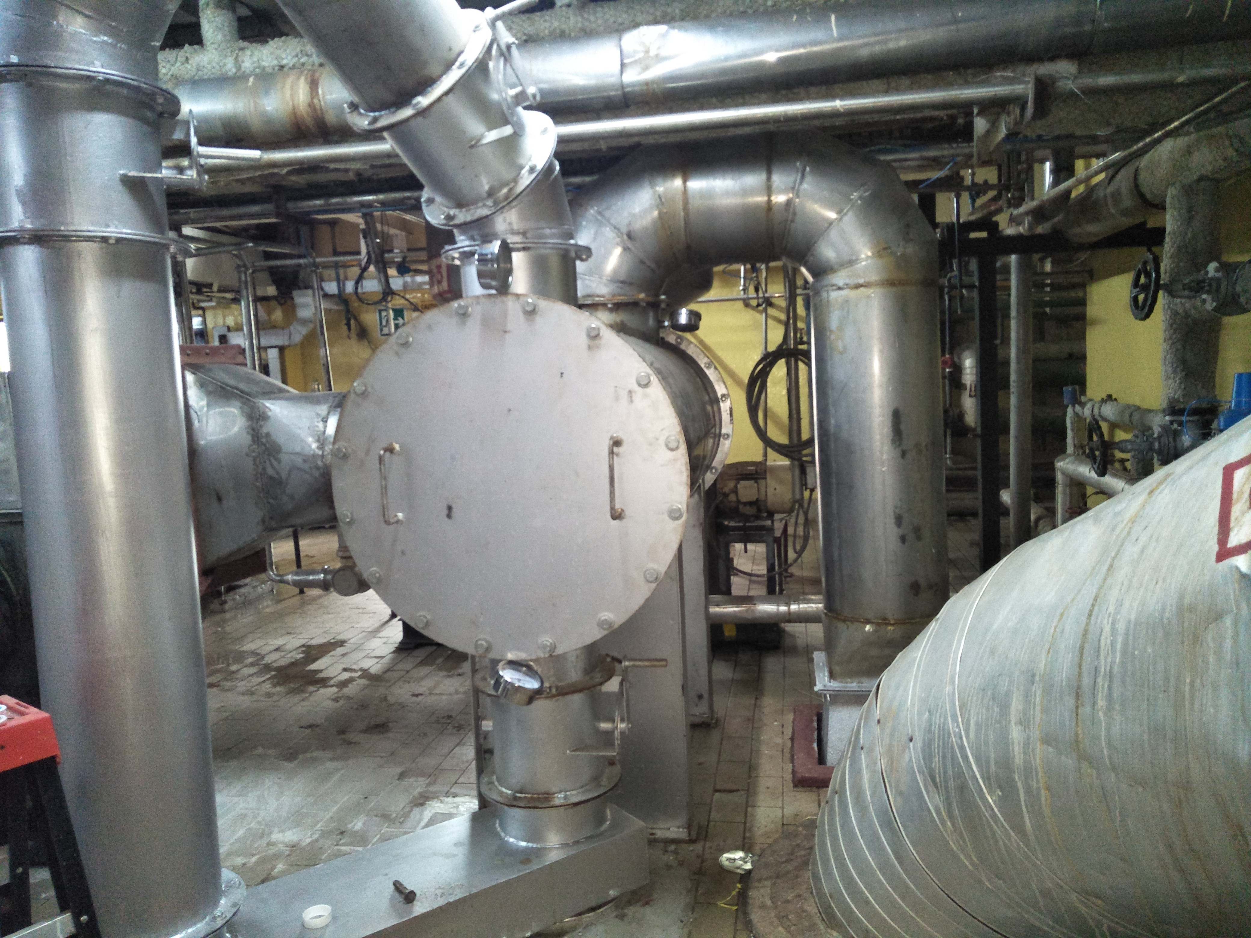 | Flue Gas to Air Heat Exchanger - HUL Ettah, Delhi HEAT EXHANGER is a device used to transfer heat between two or more fluids. There may be direct or indirect contact between the fluids. View product → |
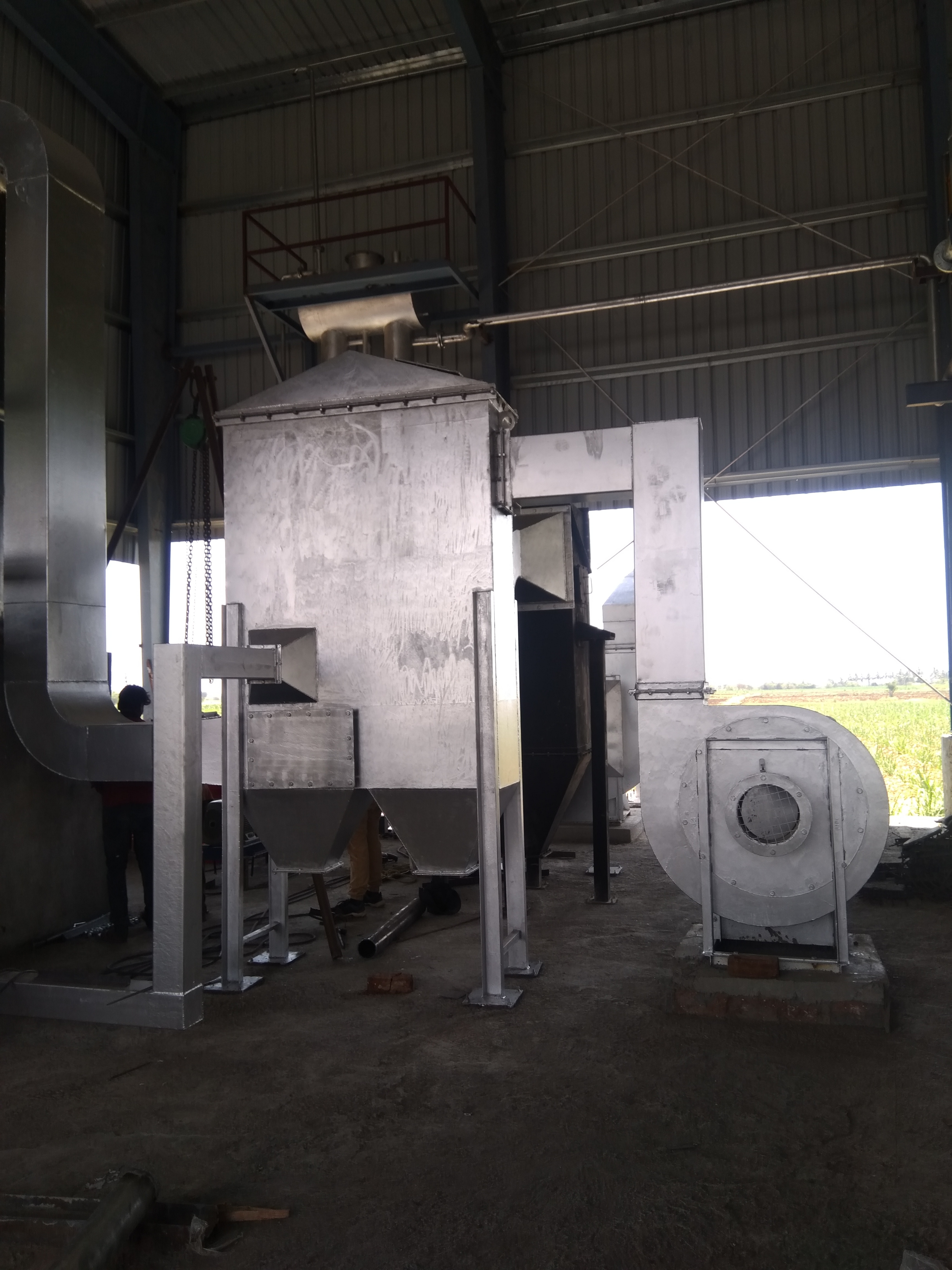 | AIR PRE HEATER An AIR PRE-HEATER (APH) is any device designed to heat air before another process (for example, combustion in a boiler) with the primary objective of... View product → |
Frequently asked questions
How do you prove that a flue gas to air heat exchanger is underperforming?
Calculate Q = ṁ × Cp × ΔT on the air side and, where reliable gas-flow data exists, on the flue-gas side. Compare both duties with the original design duty rather than relying on outlet-air temperature alone.
How can pressure drop reveal fouling in a flue gas heat exchanger?
Compare current pressure drop at the same flow and load with commissioning or design values. A higher drop points toward blocked passages, ash deposits or damaged flow paths; inspection confirms the location.
What should you check when fans, dampers or draft are causing poor heat recovery?
Check fan speed, rotation, inlet restrictions, damper position and actuator travel. Measure draft and airflow under operating load, then inspect bypass dampers and seals for leakage around the exchanger.
What causes corrosion and cold-end problems in an air heat exchanger?
Flue gas that cools below its acid-dew-point temperature can condense on cold surfaces. Check metal temperatures, condensate evidence, fuel sulphur, water or soot ingress, drain condition and areas with visible thinning or leaks.
Related products
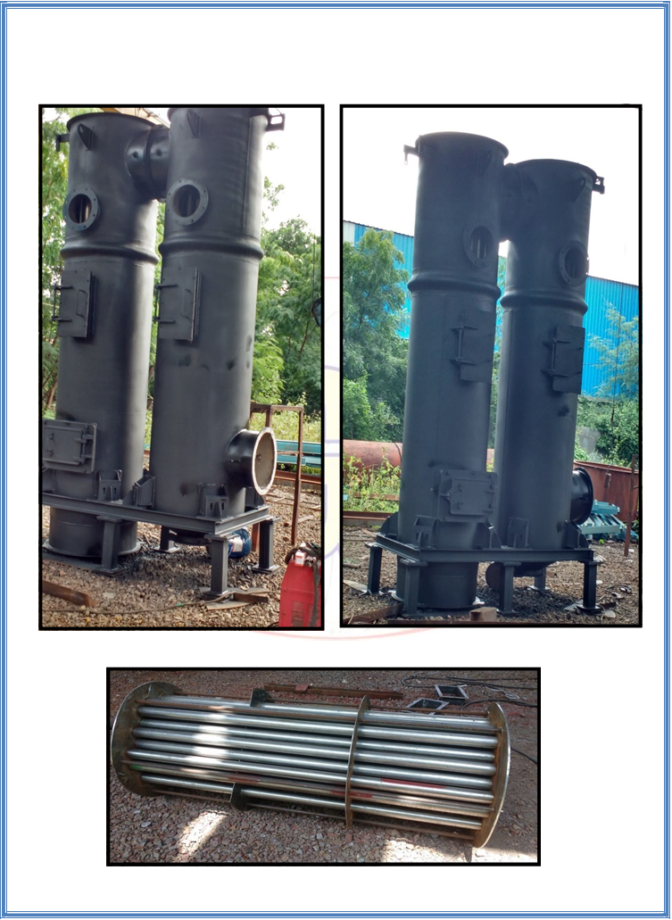 | WASTE HEAT RECOVERY A RECUPERATOR is a special purpose counter-flow energy recovery AIR HEAT EXCHANGER positioned within the supply and exhaust air streams of an air... View product → |
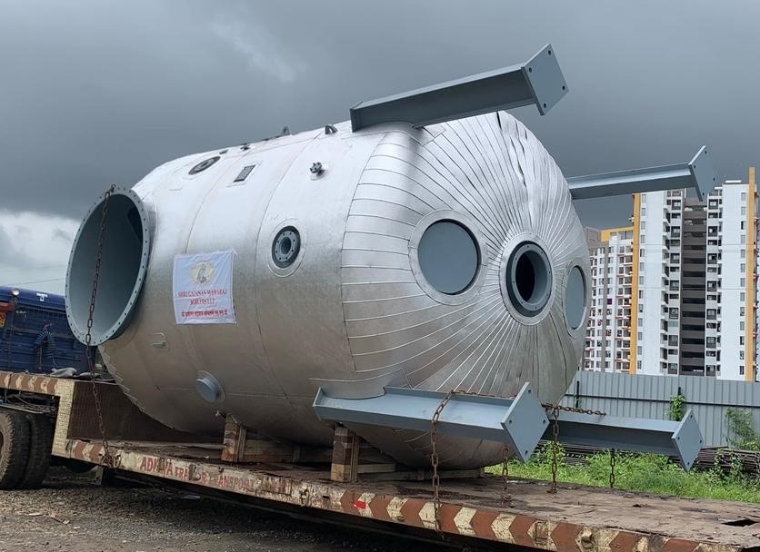 | WASTE HEAT RECOVERY SYSTEM WASTE HEAT RECOVERY is a process of recovering ENERGY from waste process outputs. View product → |
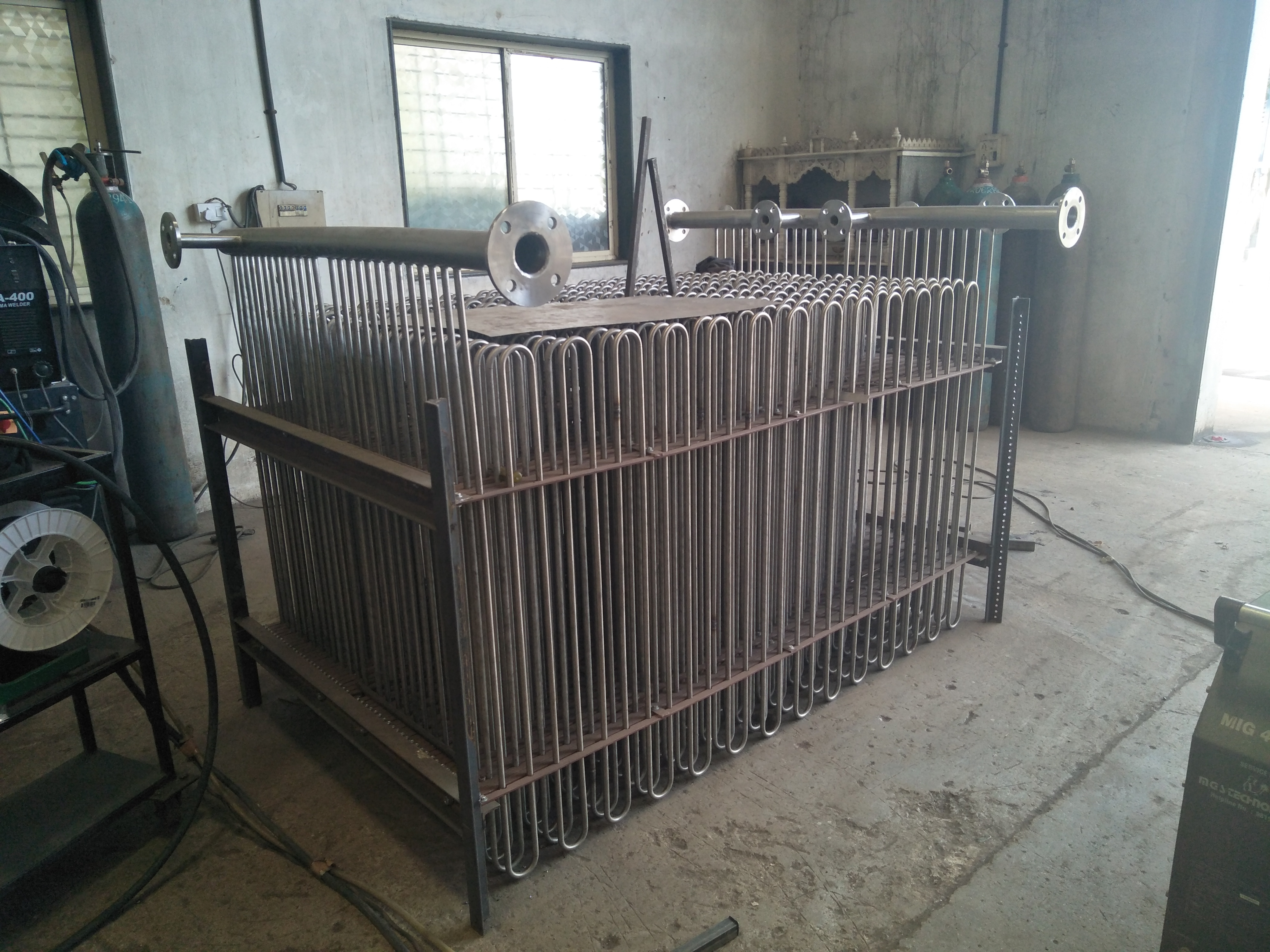 | ECONOMIZER An ECONOMIZER is a device which is used to reduce the energy consumption in the system by utilizing energy from process outputs. View product → |